
Chapter 4 is hard only because you are cutting your teeth on a whole new project and you are very unsure of what you are doing. You sure don't want to make a mistake! Yep, I have been there and done that.
One of my biggest problem was finding bulk head #F28 on the drawings. I found It on page M-4, sideways, and then, only at 1/2 length at the very right edge going up and down by the spine of the drawing. Once you finally recognize what you have, it is relatively easy to see as all of the other stuff on the page.
Your next hurdle is when making the forward landing gear bulkhead. At station 110.25 there are couple of things to note. On the landing gear bulkhead take a highlighter and highlight that you don't put the 3 plies UND FWD face and 6 plies AFT face on outboard ends until after you have installed the bulkhead in the fuselage. But you DO put the 2 plies BID and 1 ply UND after foam is cut out and glued together.
If you are making the wide body FG, on the aft landing gear bulkhead, you will extend out the 22 layer hard point out to the longer end, not move it out to the end. Thus, instead of the hard point being 5 inches it will be about 8 inches. Same goes with the AFT landing gear bulkhead drawing on page M-6, the hard point is made longer not moved over. It appears that the landing gear is the same for either fuselage size. So the attaching distance is the same, not moved out because of the wider fuselage.
Also the top forward bulkhead on drawing M-5, the one with the 22 ply hard point in it came out 1-1/4 inch too short. So when you make your part, I recommend making each one about 3/4 inch longer. Maybe we did something wrong? Id Rather sand or cut a little off, it is easier.
One other thing to add right here. All bulkheads WILL be too long or too short, don't fret it. You will soon see one of the many beauties of a composite construction. Flox and foam and sand paper will become your friend. And also get used to seeing BID and UNI spelled many different ways in the plans. Are those three abbreviations THAT hard to get right? Youll also see other type-O that will make you grin. One of my personal favorite is in chapter 6, page 5-- about half way down. It tells you to add spacers if needed to maintain queerness. Really?
Don't forget to peel ply everywhere that you will be putting another layer of glass over the item! You don't have to but youll sure wish you had. It will be a LOT easier later. Just do it!
One last note, on the AFT landing gear bulkhead, make it as shown in the plans. On ours, we had to trim ¼-inch off of the top point on each side of the bulkhead. Then we had to do some tapering to meet the existing point and notch at the root of the hard point to allow the fuselage to fit the firewall. Make the width about what the book advertises it should be. Per plans it simply seemed to flare the fuselage out too much at the top. In the picture where my finger is pointing where we had to take off ¼-inch on each side but made a line to the thumb to remove nothing. So you are taking a very thin pie shaped piece out. You do whatever you want to make it work for you.
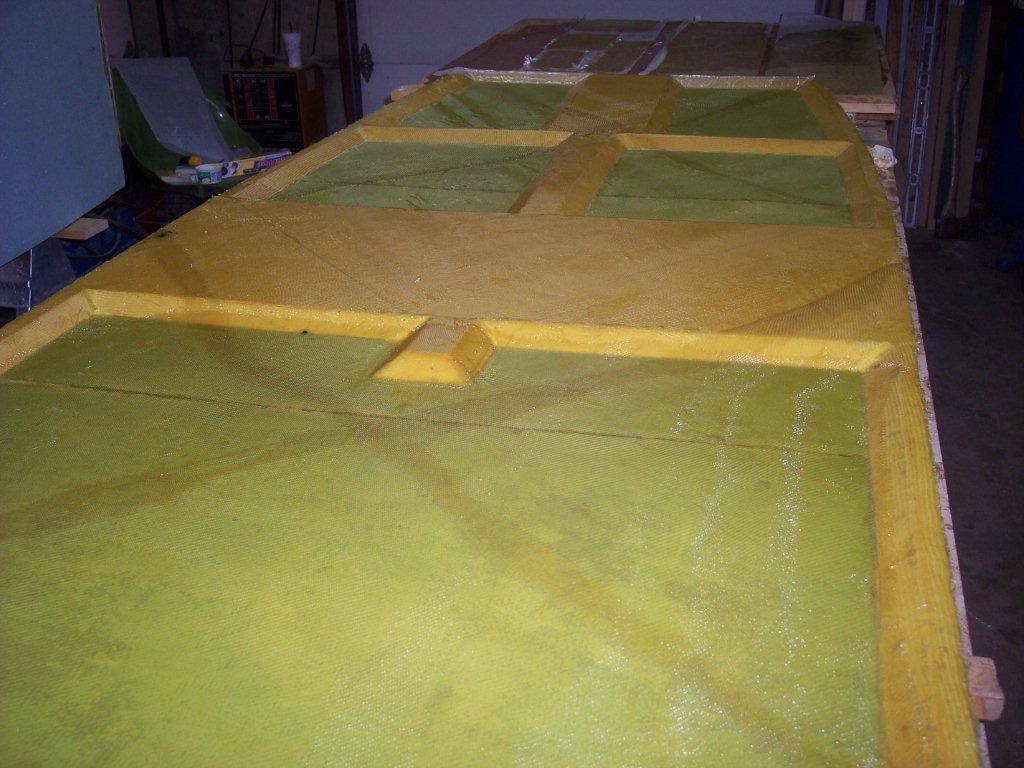 |
This is a picture of the glassed floor waiting for the 3 or so hours before we flip it over and place in on the fuselage. As you can see we placed the BID at 45 degrees with the second layer placed at 45 degrees the other direction. The rear floor has a third layer placed on it and the BID can be placed at any angle. We chose to place the simple way and it also got one other direction in the BID, we placed it "0" degree angle. Remember to let the front end of the floor have about a inch of wet BID hanging over the end. When you place the floor on the fuselage this 1-inch end will be squeezed between the aft side of F22 and the floor you are installing. Be sure to sand the back side of F22 and then we painted a little resin on F22 just before we install the floor for the glass to get a good adhesion. When we first layed the glass on the floor with all of the un-eveness we where not having even a little fun getting the glass to lay down with out a ton of air pockets. We added a little resin to the air pocket and took our squeegee and started in the middle of the air pocket and went from the middle in all directions from it and it would pull the glass out and let the glass lay fat to the floor. | |
| Dennis trimming the floor after laying the glass on it. You can see the BID tape being made to attach the floor to the fuselage. | 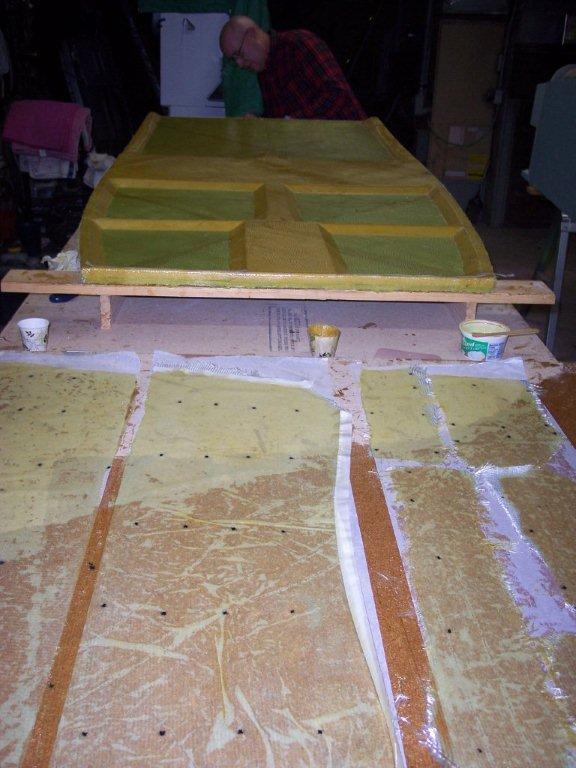 |
|
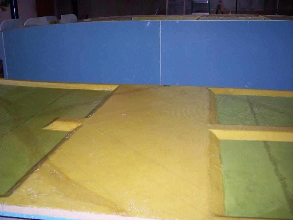 |
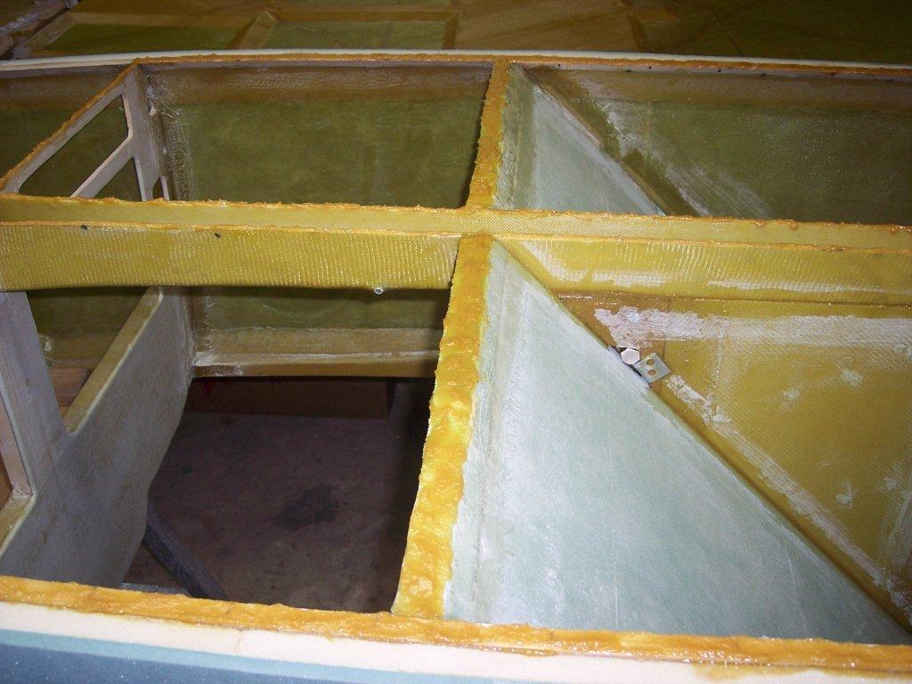
A side view of the floor where the speed brake is located. It's been glass and we are waiting 3 or so hours to place the floor on the fuselage in the background. | |
The fuselage with the flox in place ready to have the floor placed on it. You can see F22 shinning where the resin was placed to hold the glass on the floor that is pinched between the front edge of floor and the aft side of F22. |
 |
|
 |
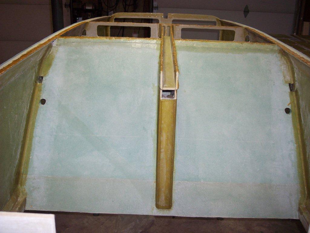
Side picture of flox on heater air duct and bottom of seat back. |
|

| Landing Light |
As it turns out, finding a suitable landing light is turning out to be a real challenge. Richard has been searching the internet for something real bright, but with minimal heat. He found a source for a LED landing light, but has been unable to make contact with the sellers. Possible Sources: http://www.strobesnmore.com/ |
|
| Tie Down Points |  Hidden Tie Down Attachments are the preferred way to deal with this. However, if this is not an option, then we just put some type of eyelet in. We must be able to protect the A/C from strong winds. Hidden Tie Down Attachments are the preferred way to deal with this. However, if this is not an option, then we just put some type of eyelet in. We must be able to protect the A/C from strong winds. |
|
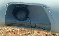 We're thinking that we want to incorporate some type of landing light in the wing. Something like one sees in this picture.