Chapter 5 will prabably be a bit easer than chapter 4. In chapter 4 everything is new to you and you found out that building an aircraft will be a very very slow process.
In fact, building a plane so much longer than people think that when friends come over to look at the project and ask how long it took to make a part, I normally tell them a number 1/10 of the actual time it took to build. For example, if a part took 15 hours to build, I just tell them it took 1.5 hours and they look at it again and figures that that sounds about right for what they see. Unfortunately and sadly to say, that 1 to 10 rule works on the inverse as well and any part Im planning to build takes 10 times as long as I thought it would take.
The jigs we made and you see below were attached to the table by drilling large pilot holes down through them, followed by long screws, rather than bondoing them down as the instructions call for. I just didn't feel that warm and fuzzy about the bondo holding them down with all of the work that was going to be done on them.
This worked well for us. I am sad to say chapter 5 was a large learning chapter for me, (not you—ME!!) I believe the problem began by laying the plans book on the work table on one side, and then moving the plans to the other side as we put the jigs on the table. All went well until a few days later we took the fuselage sides off of the masonite and the table and stood them up on the floor. Looking at the curvature of the bottom I noticed that the little short doubles that are glued on each end of the upper longeron were on the wrong end. So the next night that my partner was there I showed him the problem and told him to look at the plans and tell me I was wrong. Well he said that he was happy to inform me that I was wrong-- sure enough...... but he was also sad to inform me that the whole thing was wrong. And he meant the WHOLE thing was wrong. So the completed pieces went in the trash.
So that saying, "measure twice and cut once"-- It applies in a lot of other things other than just cutting. The only other thing worth mentioning here is that we made a small change in Chapter 5. We heard from a lot of builders about a clearance issue with the electrical duct that comes out at the firewall and how it was so VERY close to the rudder cable pulley. So, we lowered it closer to the lower longeron, maybe a 1/4 of an inch.
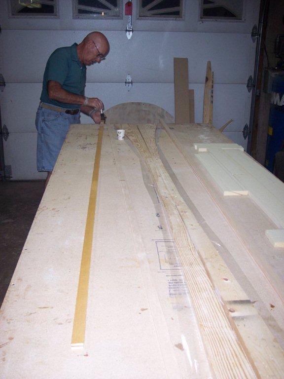 |
In this photo we are putting resion on the three strips of birch wood that will become the upper longeron. They are going to be placed together and tightly pressed together next to the forms that you cut earler to make the right conture for the upper longeron. They will be held tightly to the form by driving many nails into your table on the open side of the strips to let they harden so they will keep there shape. | |
| Now you can see the two sets of upper longerons that have been placed next to the forms and the birch is tightly held in place by the nails until they harden into the correct shape. | 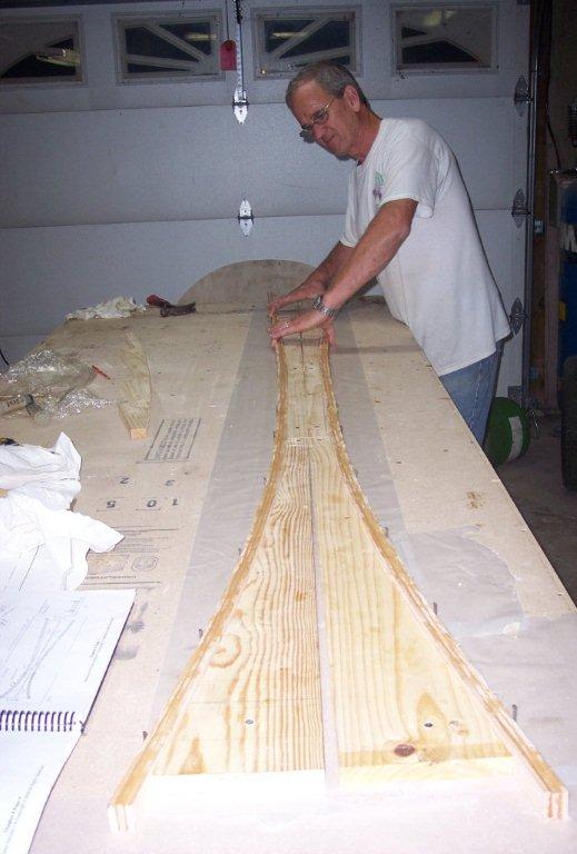 |
|
 |
A day has passed for the upper longerons and we are now ready to pull the nails and see that the birch strips that were once straight are now permanently bent into the shape of the upper part of what is going to be the upper fuselage. | |
| In the next step you will be making the upper longerons to shape the upper part of the fuselage. First you will follow the plans book to make the correct shape in 1 X 4 pine from the local lumber yard. You will cut contours in the wood in sections, keep the sections lettered because later you will use some of them again to make other contours in other parts of the fuselage. You will letter each section so when the plans book tell you which one to use and where, you will know which ones you need by the letters you places on them. | 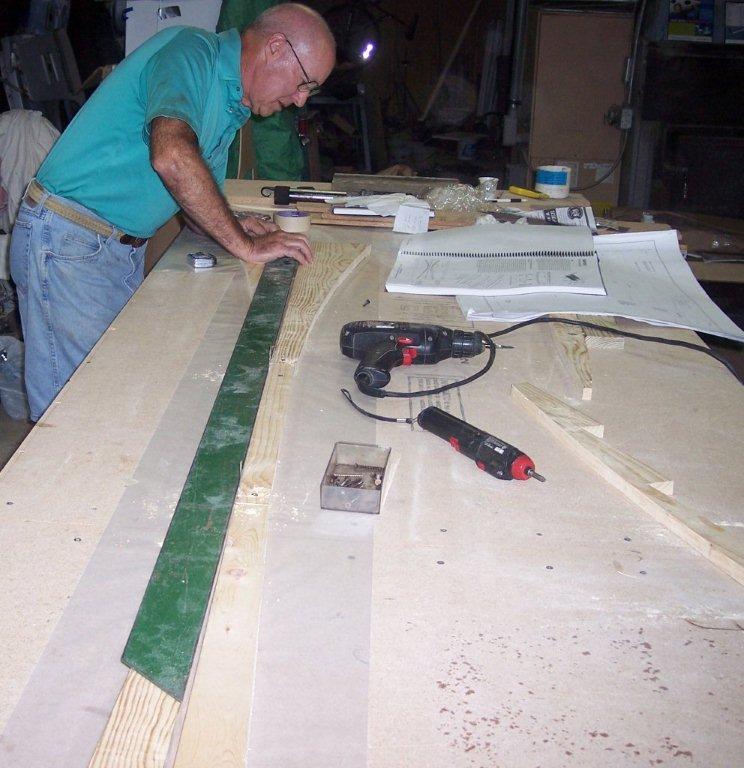 |
|
 |
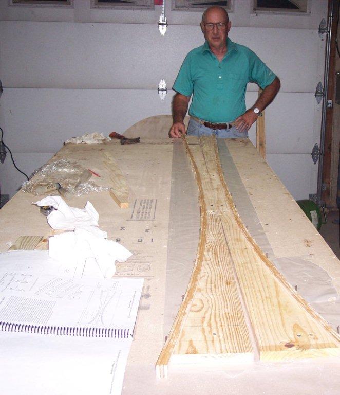
Some of these 1 X 4 pine boards are the ones you saw us cutting a few pictures ago to make the upper longerons. Now we are useing some of them again but with a couple of different one mixed in the change the curve just a bit to form the lower longerons on the sides of the fuselage. As you see these boards are layed on edge, not an their side like before. I drilled holes down through the board and screwed them to the table so they would not move. The plans tell you to use 5 minute expoxy or use bondo to hold them down but I trusted screws instead. | |
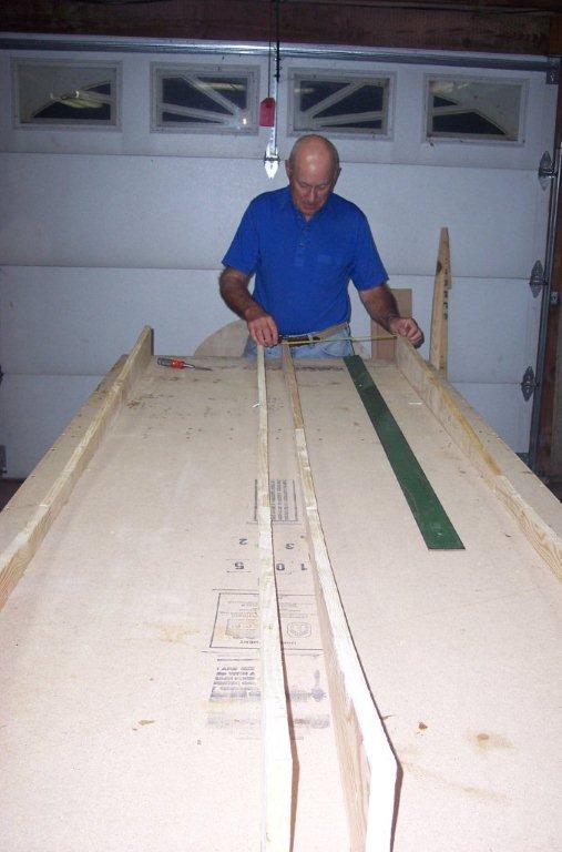
After getting the forms made for the shape of the sides of the fuselage you will get 1 sheet of masonite from the local lumber yard. Then the plans book will tell you where to place the marks on the masonite to make the curve for the bottom of the fuselage on this masonite. There will be just enough left over between the two sides to get a scrap that will be "just" enough to flox it on to the aft end of the masonite to get the full length. Now you have many marks to follow to make a smoth profile as you cut the masonite, I used a tape stripe to make a flow from each mark to the next. With the tape I could see the transition from mark to the next mark to see if it was a smooth flow from one end to the other end. |
 |
|
 |
We have made the forms for the upper longerons and then made the longerons, and then we used some of those same forms but replaces a couple of them with a couple of other ones we did not use yet. We attached the forms to the table and then we attached the masonite to the forms. Next we used bondo to attach the forms to the masonite so they won't move and to keep them contoured to the masonite. | |
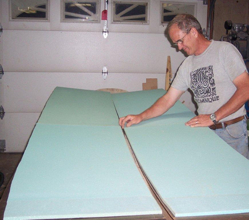
| Now we are getting ready to cut the foam that is going to be attached to the foam that we just attached to the masonite in the previous step. The plans book tells you where to draw the lines to get the right angle when cutting the foam. I found that the easiest way to do this is to lay a piece of straight metal along the edge of the work table. I used a sheet of metal that I got from a heating/cooling company that had a a straight edge and was about three feet long. Place the line on the foam that is the farest out of the cut you are making is on the edge of the metal. On the line that is lined up on the metal on the table, bring the line up the side of the foam a little so you can see it without having to look up under the foam to see if you have it lines up. Then take a hack saw blade in your hand and place the blade agains the metal on the table and line the top of the blade with the line on the top of the foam. Cut away, doing this you will have the perfect cut. | 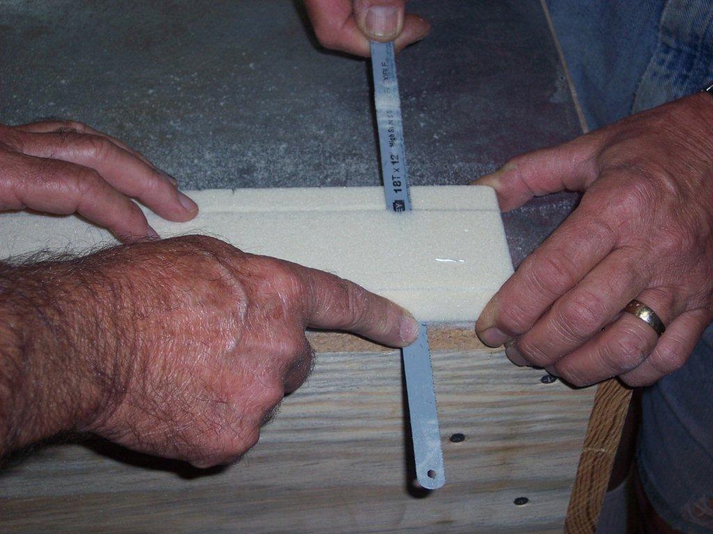 |
|
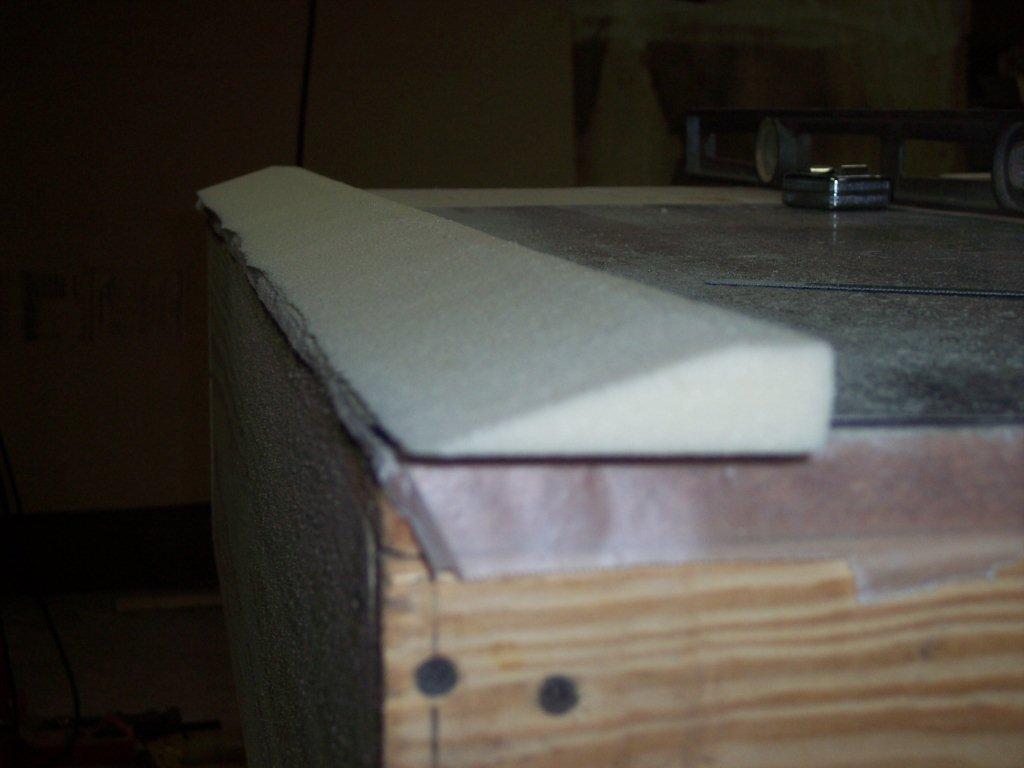 |
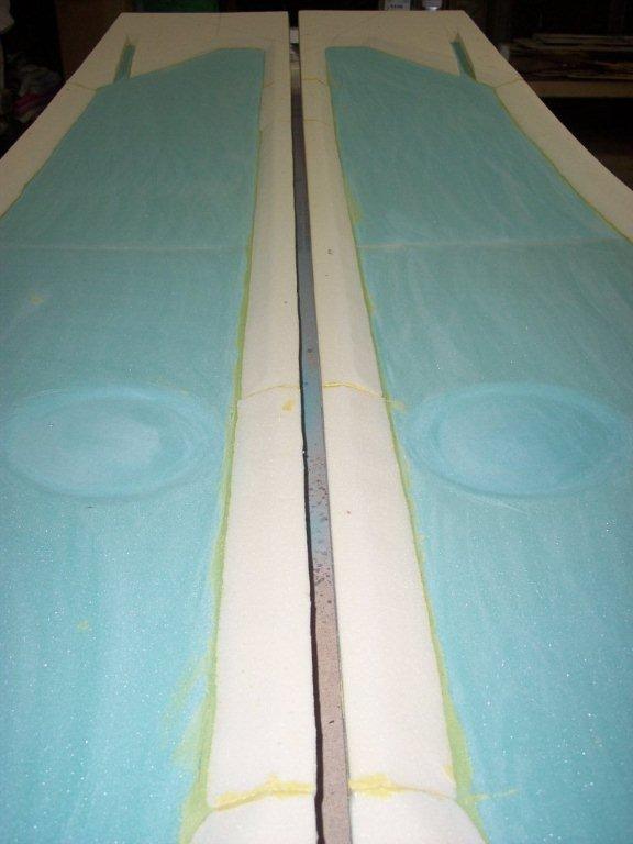
You can see how the foam looks after you cut the angle as descrided the the previous step. | |
Now that you have cut angles on a lot of foam it is time to micro them up and attach them to the foam that is the sides of the fuselage. You will need to take a bunch of small nails to keep them "pinned" down to the curving blue foam so they will dry tight to the blue foam. You will need to place a lot of the nails at a large angle so they won't want to pull out.
|
 |
|
 |
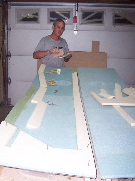
Here is what it will look like after you have cut out all of the foam and placed it to the blue foam. You may notice the rather sharp curves in the foam at the front of the picture. You will need to make a semi-circle where a turn is made and the use something like a jig-saw blade to make such a sharp corner. |
|
| Now we need to make two circles where the joy stick is located for controlling the aircraft. Some people used a router, but I used a disc sander and used a seven inch sanding pad. I first took a marker and marked the outside of the circle I needed to make so I knew where to stay wile sanding out the foam to be removed. | 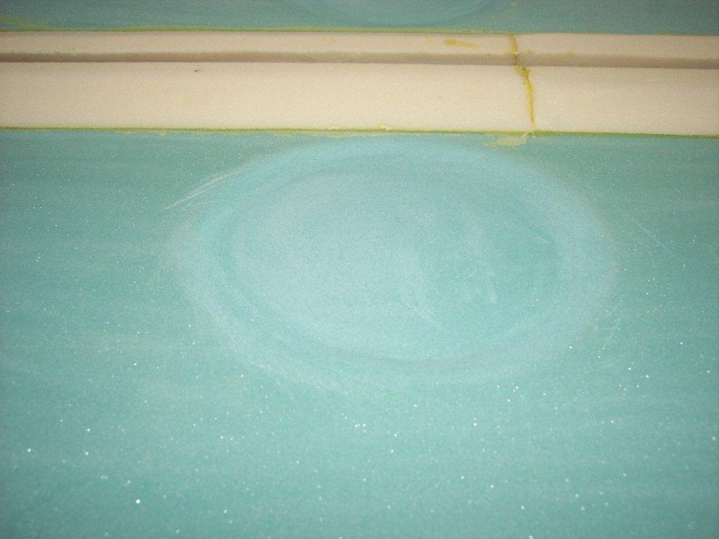 |
|
 |
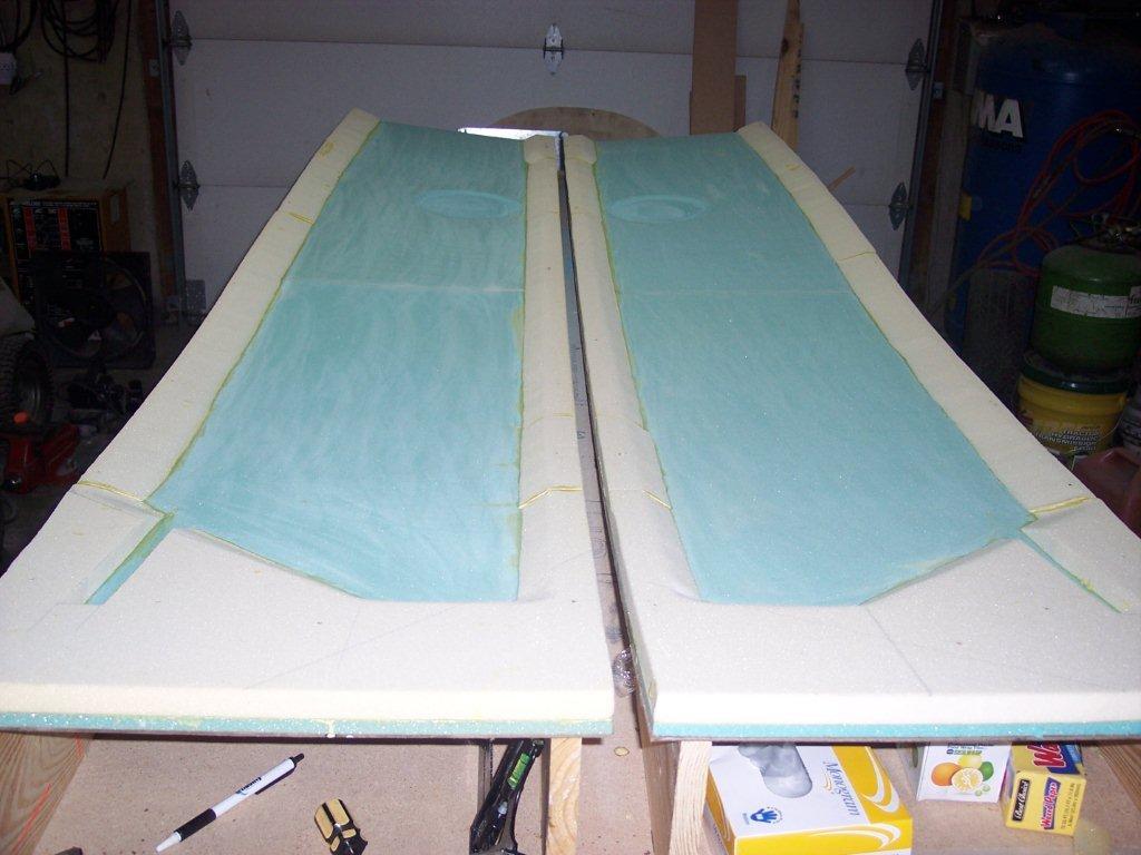
Here is the fuselage with the foam microed to the blue foam and the circles placed in the sides of the blue foam. | |
| Now is the time to put the UND glass on the fuselage at 30 degrees and the next UND is placed the the other direction at 30 degrees. Remember to be sure not to leave any excess resion on the lay ups. At the end of the project a lot of pounds can be added to your airplane | 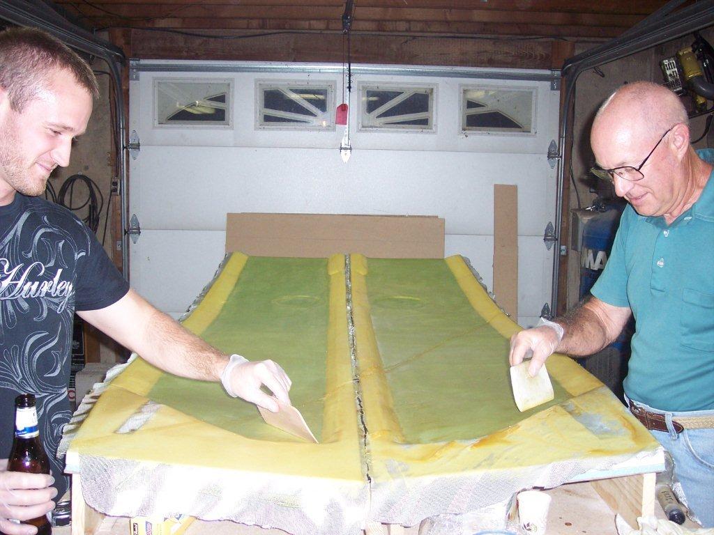 |
|
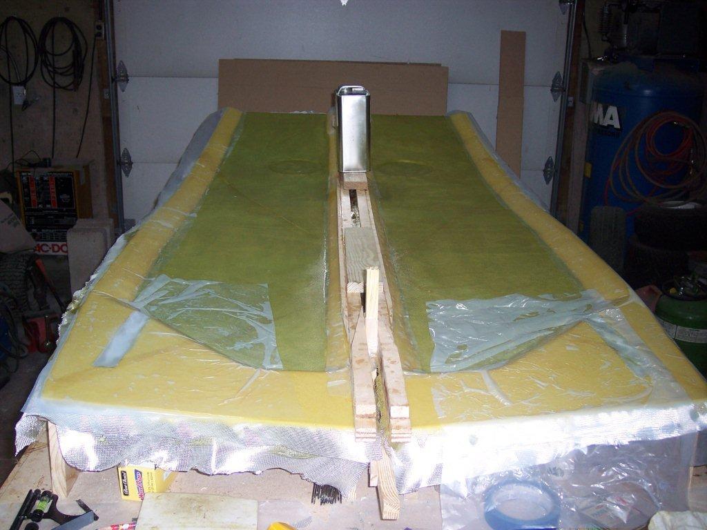 |
Well, it is all glassed up and we are letting it harden. You can see all of the peel ply on the aft end because a LOT of additional layers of glass will be added in the rear area through many chapters. | |
| Chapter 5 completed! | ||
| To see a complete set of pictures, click HERE |

| Landing Light |
As it turns out, finding a suitable landing light is turning out to be a real challenge. Richard has been searching the internet for something real bright, but with minimal heat. He found a source for a LED landing light, but has been unable to make contact with the sellers. Possible Sources: http://www.strobesnmore.com/ |
|
| Tie Down Points |  Hidden Tie Down Attachments are the preferred way to deal with this. However, if this is not an option, then we just put some type of eyelet in. We must be able to protect the A/C from strong winds. Hidden Tie Down Attachments are the preferred way to deal with this. However, if this is not an option, then we just put some type of eyelet in. We must be able to protect the A/C from strong winds. |
|
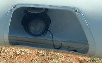 We're thinking that we want to incorporate some type of landing light in the wing. Something like one sees in this picture.