 |
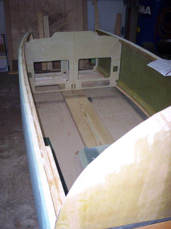
Pic 1. Here's the start of chapter 6 for us. We have the temporary firewall installed, and we have installed F22 and F28 and the instrument pannel by floxing it in. Here is where you will find that a sander and flox will be your friend. It makes no difference how good you do all of the bulkheads and seat back you will have to sand some and flox some to get them to fit as they should. | |
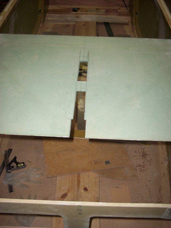
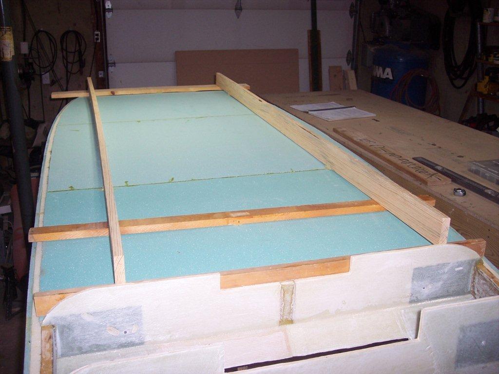
| In this picture we have carefully cut out the opening that will be the place the wing spar will be placed in. Earlier when you were building the fuselage sides you were told to carefully install wooden brace LWX and LWY to precise dimention. Here is where you cut out the area 5.5 inches by 8.7 inches where the braces LWX and LWY are at to help support the wind spar in a later chapter. | 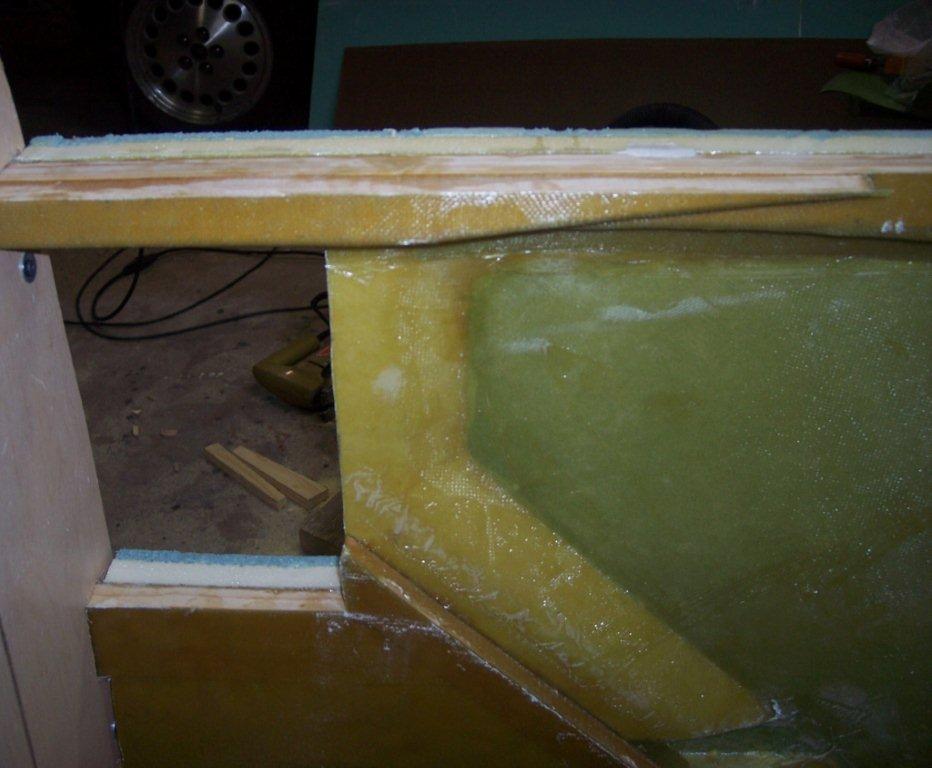 |
|
|
We have sanded and floxed to get the seat back installed and it is being held in place with a ratchet strap until the flox hardens. One thing we found out a little later is to get the top of the seat back located at the right place and even with the top of the upper longeron. So far so good, then we placed the seat back at 45 degree angle and floxed it in. When we went to install the floor we could then see we were about 3/8 of a inch of being even with the floor with the seat back. So we had to install a thin strip of foam between the bottom of the seat back and the floor when we installed the floor and BID taped the two together. So don't get so hung up on the seat angle but get the top and bottom even with the upper and lower longerons. | |
| Just a front view of all of the bulkheads installed and seat back just been flox in and the ratchet strap holding the sides tighty together. | 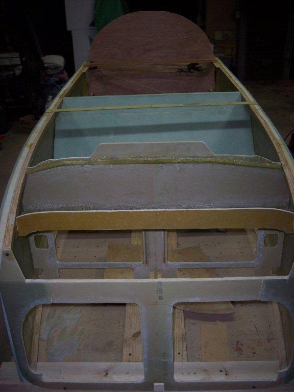 |
|
 |
Just a picture of the front side of the seat back and you can see the map pocket and the airduct/center console cutouts in place. | |
| Her we are once again rechecking that everything is straight and level. Can never be too sure about that. After that we sanded and floxed the forward and aft landing gear bulkhead in place. | 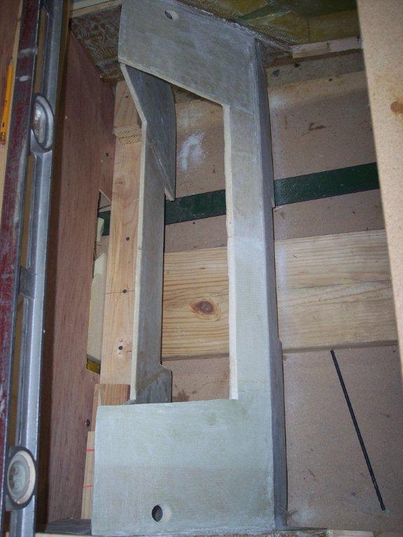 |
|
 |
Another picture of the forward and aft landing gear bulkheads being flox in. BID tape will be installed on each end and both sides of these to bulkheads. There will be lots more fiberglass installed on these bulkheads along with the firewall so you need to peel ply most everything back here. You can bet that that won't be the last layer of glass whenever you put more glass down it this area. | |
| We are now constructing the front seat back brace which includes the map pocket. You first cut out the foam and then glass the insides of the foam. Then you flox all of the small parts of foam together to get one side of it solid. At this time I went one additional step and put some BID tape along the map pocket joints that weren't called for but we added some for added strength. | 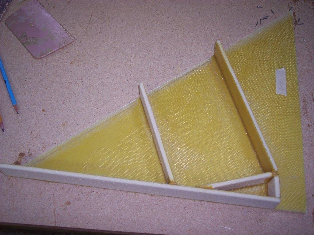 |
|
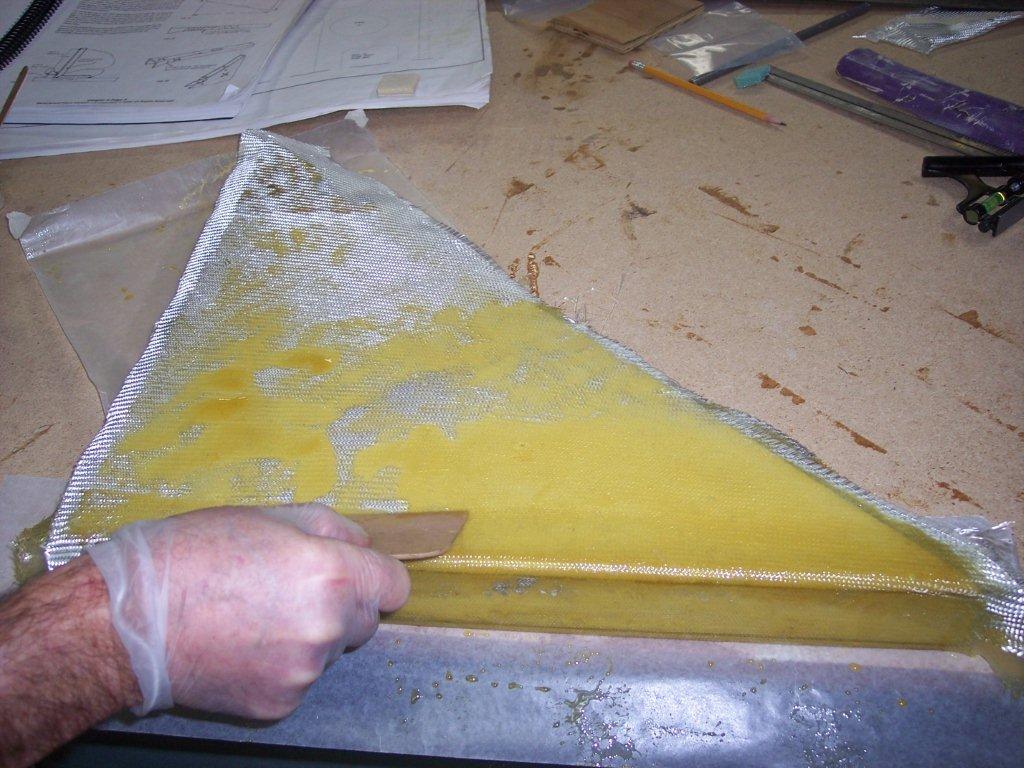 |
It is hard to see in the picture but at the far end we cut the inside of the glass to then scraped away the foam only to leave the outside layer of fiberglass. This is where you insert the triangler piece of plywood that houses the fuel selector valve. | |
| In this picture we are making the front center heater air duct. I used some of the left over partical board that I made the top of the work table out of. It was made out of 3/4 inch board so I doubbled it and that gave me the 1 1/2 inche wide spacer I needed to make the air duct 1 1/2 inches wide. | 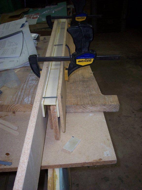 |
|
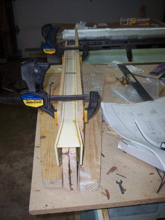 |
Here is a picture of the other end of the heater duct. Maybe you can see but I put two more scraps of the partical board to press the outside of the duct to keet is aligned and straight. I used this procedure when I flox the foam and when I glassed the outside of the duct. |
|
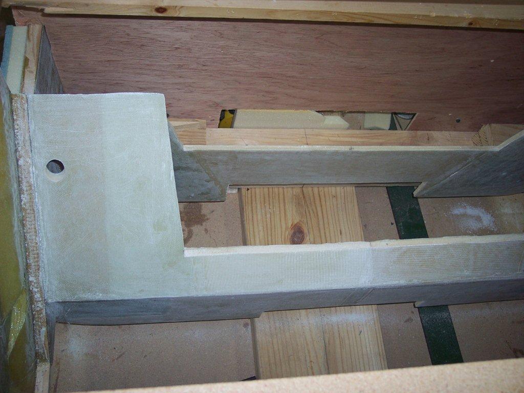
| When making the aft landing bulkhead we made it just like the plans showed to make them. We checked it 10 times at least. When it was time to fit the sides of the fuselage together and put the temporary firewall on, the firewall was not even close at the top. We looked at the plans another 10 times and check every dimension, were right on target. The bottom longerons were fine, but the top was at least a inch to wide at the top longeron. So we looked at the AeroCanard data sheets and measured the width of the upper longerons for as the interior shoulder room. It to was showed the aft landing gear bulkhead pushing the top too far apart. So we ended up cutting 4/10 inch off of the top tip of the outboard aft landing gear bulkhead off and tapering it to nothing removed at the bottom to where it makes the 90 degree turn where the lower longeron sits. After cutting the 4/10 of of the top of the aft landing gear bulkhead everything fit well. Only time will tell if this was the right thing to do, but everything seemed to fit just fine fter the 4/10 was removed. And yes we did cut out the FG firewall not the small body firewall. |  |
|
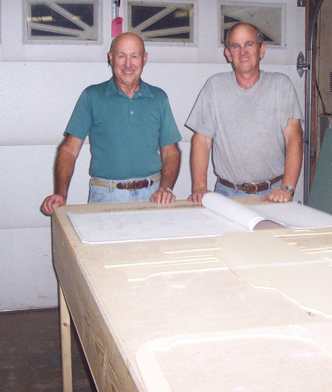 |
Meet Dennis and John. Dennis on the left side of the picture is a long time friend of mine and is a graduate from University of Missouri Science and Technlogy at Rolla. He happens to live no more than three miles from my house and that is also the location where most all of the construction will be done. There is nothing better than to have someone helping in the construction of a complicated project. Two sets of eyes, two sets of hands and two brains plus the added fun working with someone rather than by yourself makes this project so much better. He has been flying for over 35 years. That is me, John on the right the owner of the Aerocanard. I have been flying for over 30 years and this looked like the next project I needed to do in my life. The Aerocanard seemed to have all of the attributes I was looking for in a plane. I presently own a Piper Twin Comanche. |
|
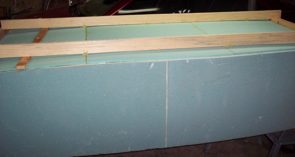
| After placeing the three pieces of foam on the bottom of the inverted fusealage we traced the longerons from inside of the fusealage. We then removed the foam and added 3/4 of a inch to the original lines drawn along the logerons. You will also be tracing more things than just the longerons when you are "inside" of the upside down fuselage. | 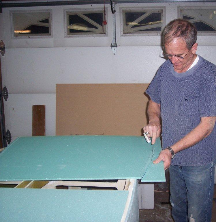 |
|
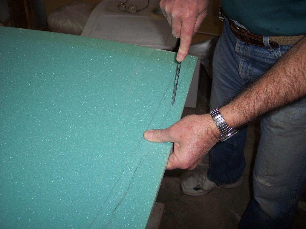 |
We are now cutting the lines to get the shape of the floor and to get rid of the excess outside of the fuselage sides. | |
| Everything look to plan and we got the three sections of foam floxed together. | 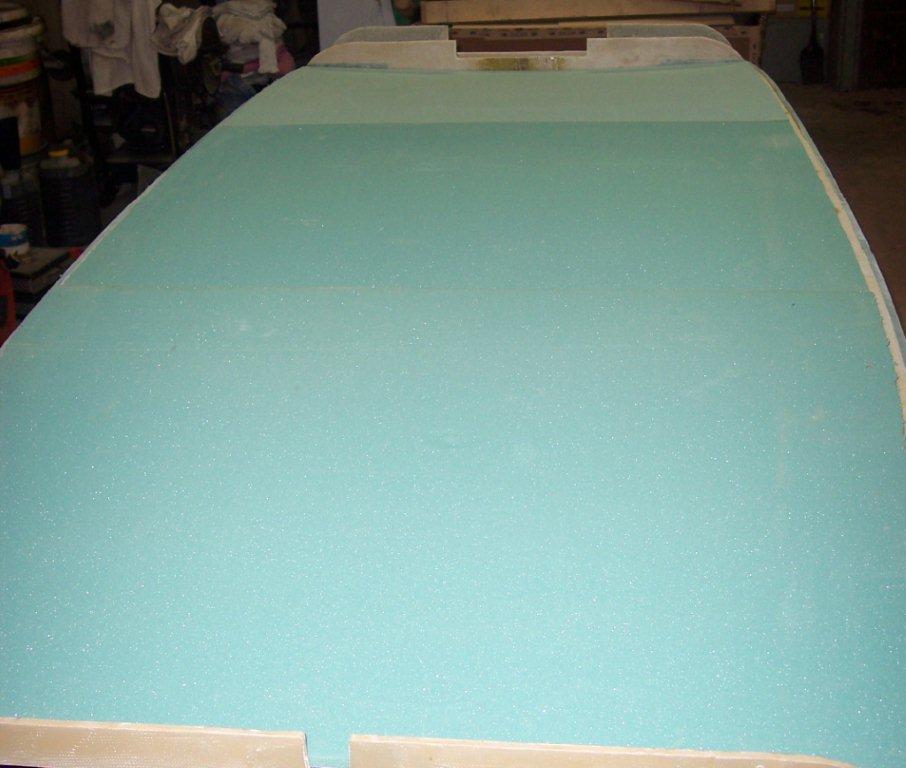 |
|
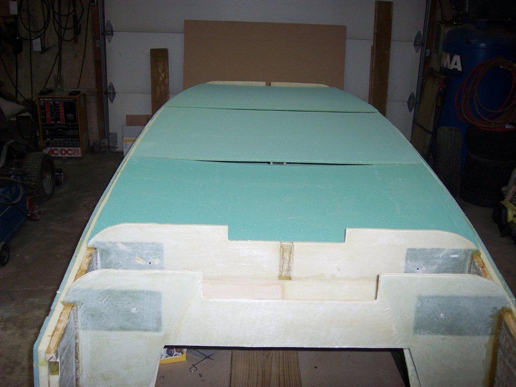 |
We have now gotten all of the lines cut to get the floor cut to shape and now we have put it back on the fuselage to make sure it looks right and to get ready to flox them all together. | |
After you get the floor cut and the three sections floxed you will then make a jig to hold the now created floor to the same shape when it is on your work table as it is and will be when it is placed on the bottom of the sides of the fuselage. Back to the lumberyard to get some 1 X 4s to make the jig. You will use bondo to make spots on the lumber to hold the spaceing correct and to hold the jug to the floor. You may have to add weight on the ends to be sure it has the foam pressed all the way down to the longerons with no air gap.
|
 |
|
 |
A side view of the jig with the bondo in place to keep the gap in place and to keep the jug attached to the foam to move it to the work table. | |
| Aft end view of the jig and the floor just before we removed the floor to place it right side up on the work table. | 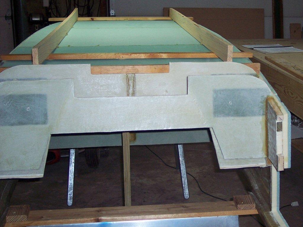 |
|
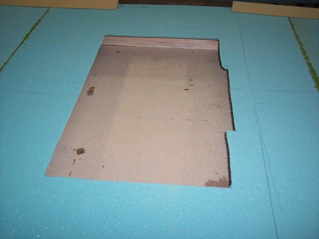 |
One of the first things you will do with the floor after transferring it to the work table is to cut out the landing brake. We used a jig saw with the blade set at 45 degree angle to make the cuts | |
| After you have cut out the landing brake you will start cutting out a lot of foam pretty much like you did when you were putting foam along the edge of the fuselage next to the wooden longerons. Except you will have a lot more of it and a lot of angles to work with. Just cut one end and look at the other end of where it is going to go and you will see which direction the cut has to be made. The book gives you all of the angles of the cuts you just have to keep track of where they go. Keep them layed out on the floor of the aircraft so you don't loose where each one goes. | 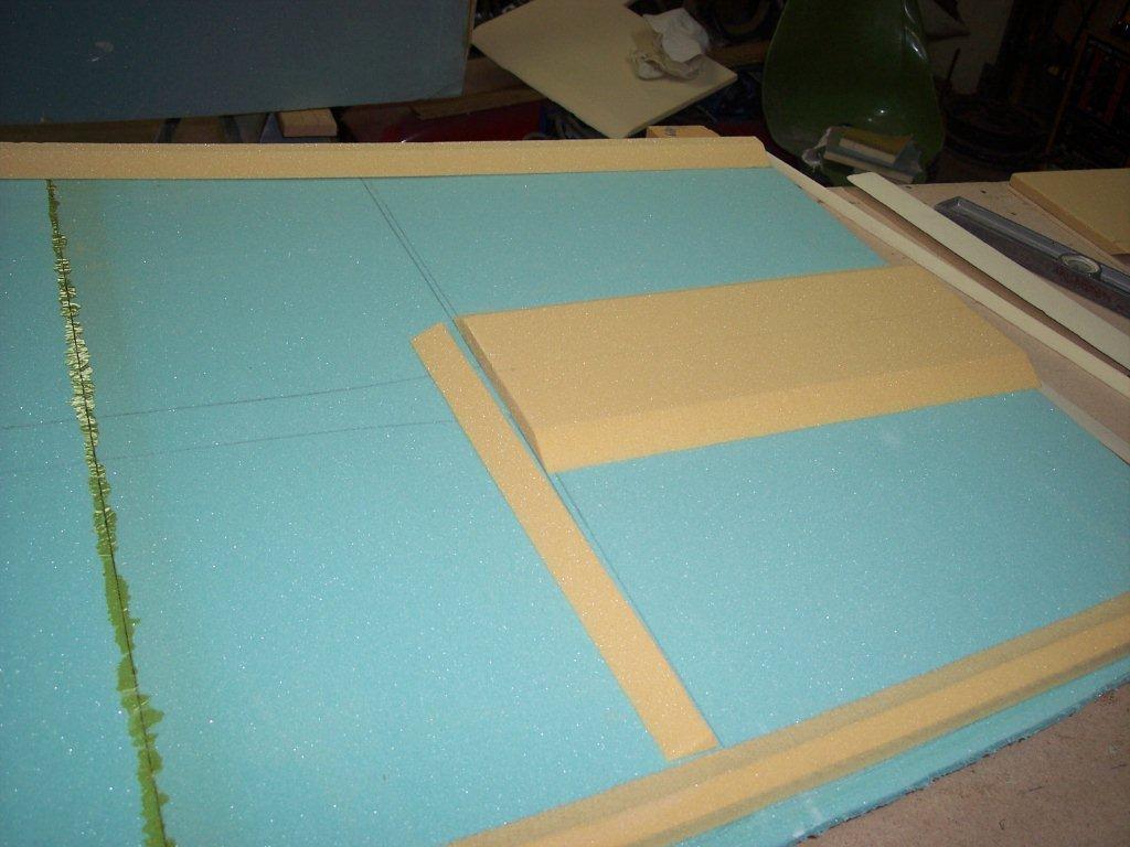 |
|
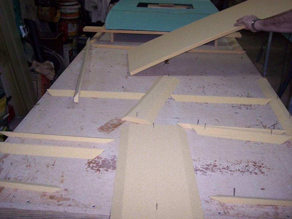 |
Here you get the idea of how many pieces of foam you are cutting out. It is a lot like a jig-saw puzzle if you loose track of which piece goes in which place. | |
| Chapter 6 completed! | ||
| To see a complete set of pictures, click HERE |

|
||