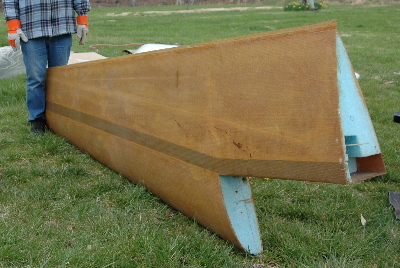
 Left— Here is a wings as it arrived with the kit. In the picture, you can clearly see that it has been skinned, but no control surfaces have been cut or is there rigging of any type.
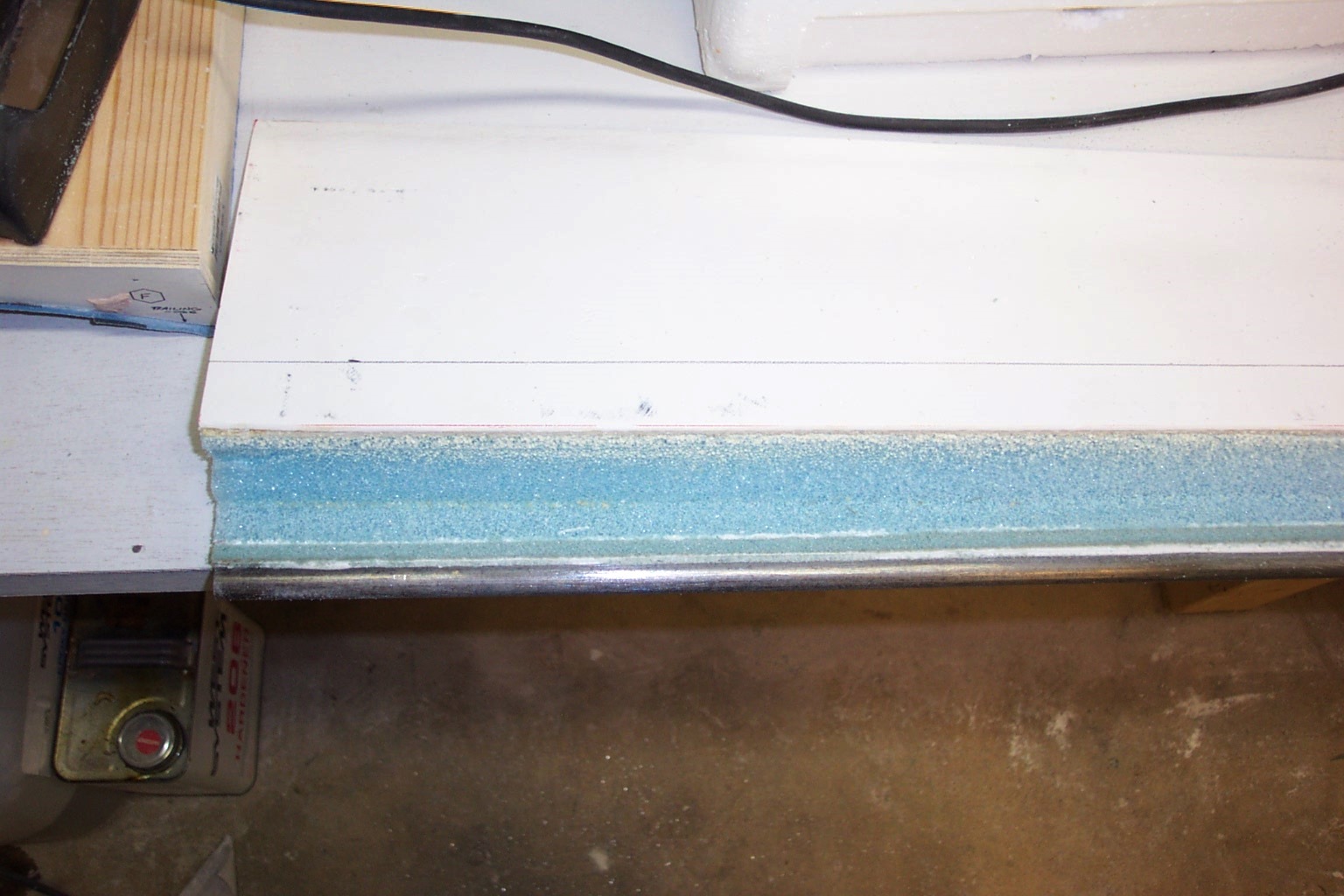
Before the Ailerons can be cut, all rough surface work on the wing needs to be completed. This include filling all low spots with a micro balloon fill and then sanding to shape. See Chapter 4 for a better account of the process. We're getting pretty good at this micro fill stuff.
We've pretty much got it down to a science on the mix process. We try to mix 100g of epoxy with another 20g of hardener. Our scale read's in 5g increments. We can usually measure out 100 grams perfectly (3-1/3 pumps). The 20g we still need the scale for. Don't worry, we use the scale for both just to be sure!
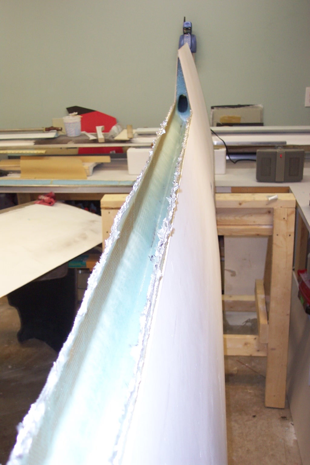
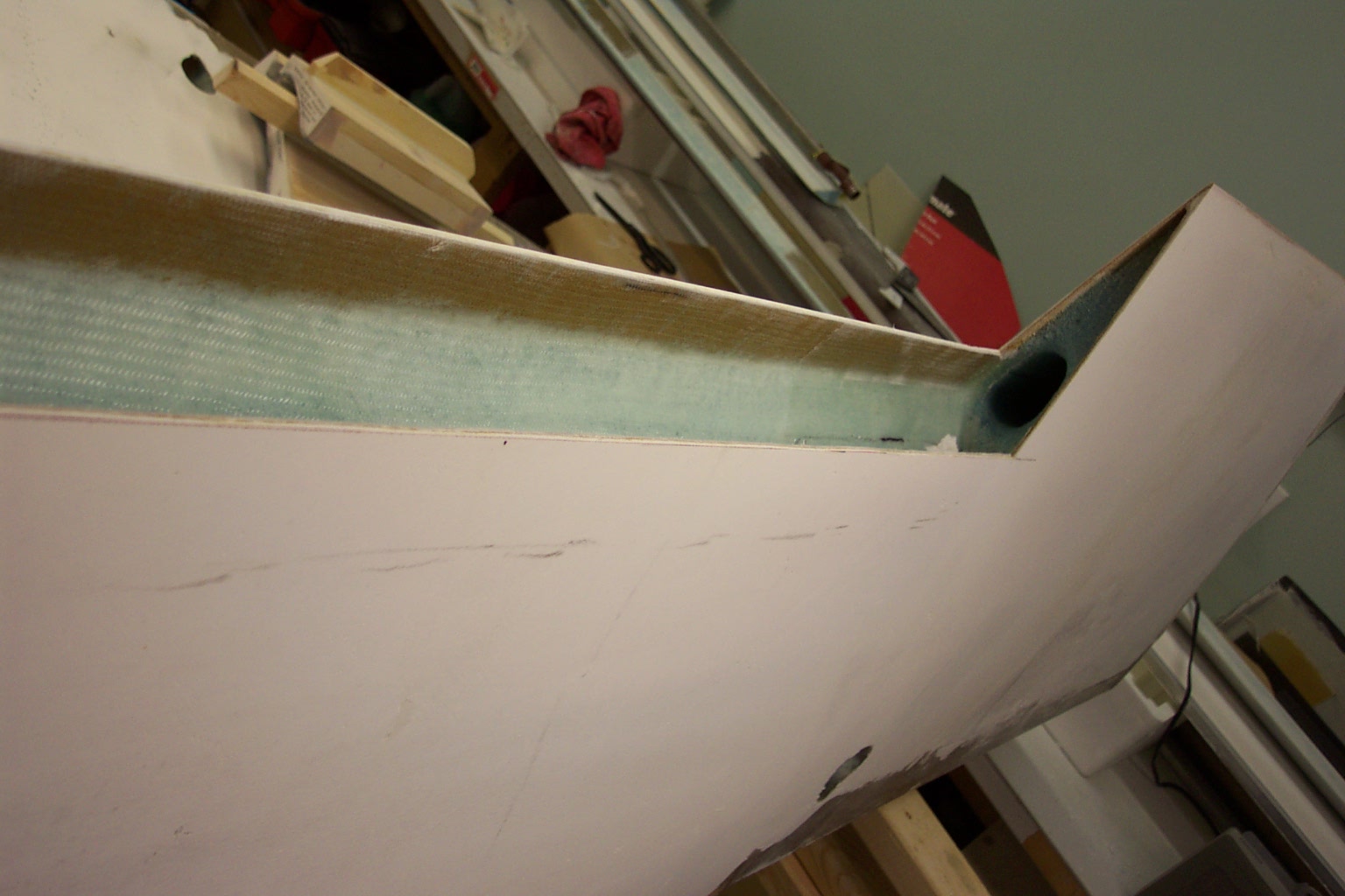
Right— In late October 2007, we cut the first Aileron out on the left wing. As you can see from the picture at the right, the cut lines came out real clean. The initial cut was made with a Fein Multimaster Saw.
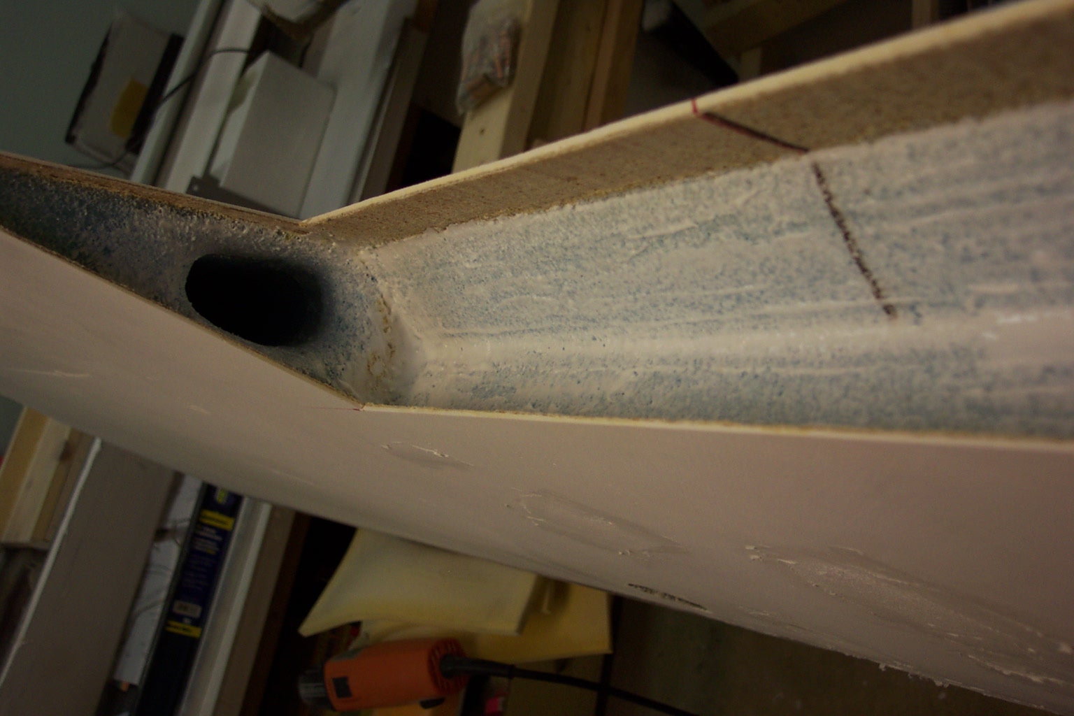
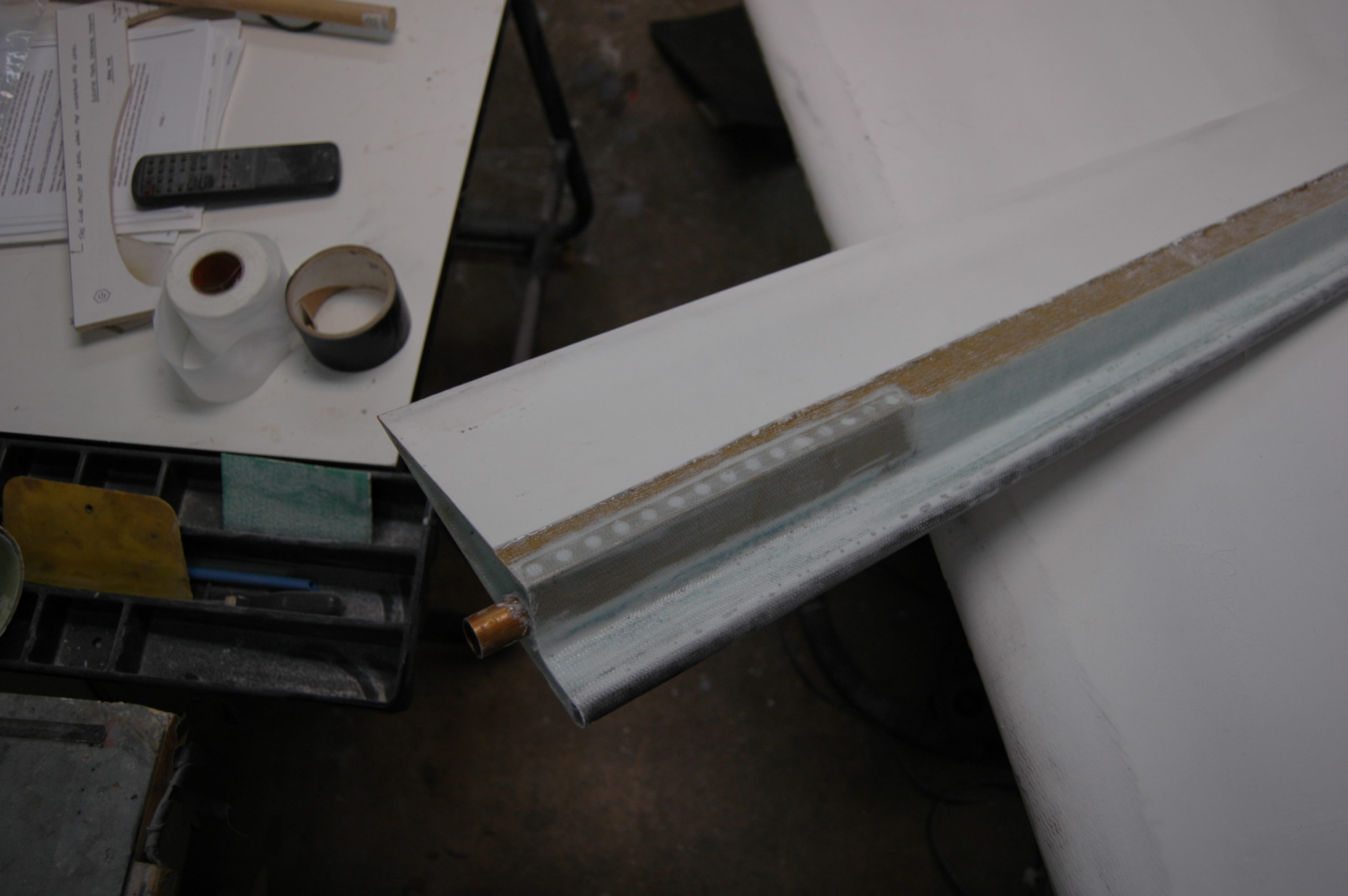
While we're speaking of tools, it might be a good time to mention a tool that is an absolute must: The Dremel style rotary tool. We use this tool to counter cut into the foam and to clean the flox off of the edges of the glass after removing foam such as will be done on the end of the Aileron end as pictured at right.
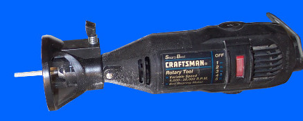
At left is our rotary tool. We keep a little router type attachment on the tool so we can monitor depth of the cutting blade. If you haven't purchased one of these tools yet, spend a few more bucks than we did and get a little heavier duty model as you will work this tool into the ground.
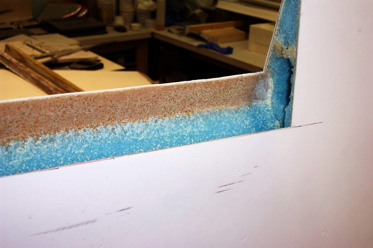
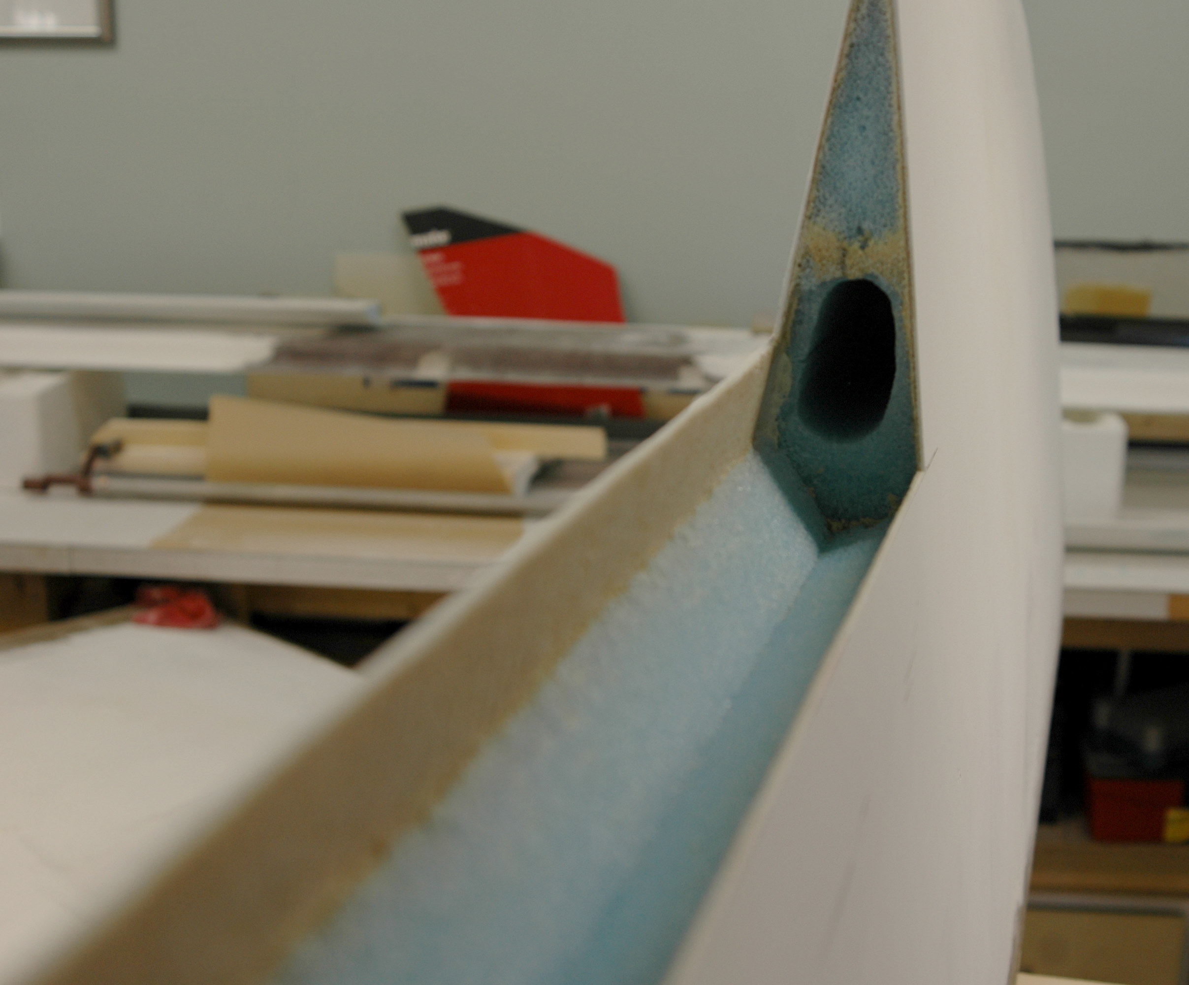
At right, we have our cleaned up Aileron cutout. As stated above the inside edges of the wing skins were cleaned up using our router tool above. The manual/DVD states that we are to look for the peel-ply on the inside skins and remove them. We never found any peel-ply on our wing cuts. Just to be sure, we made some pretty deep cuts with our Dremel tool just to make sure we didn't miss the peel-ply.
To see a few more examples of the early aileron work, click on the thumbs below.
 |
 |
 |
 |
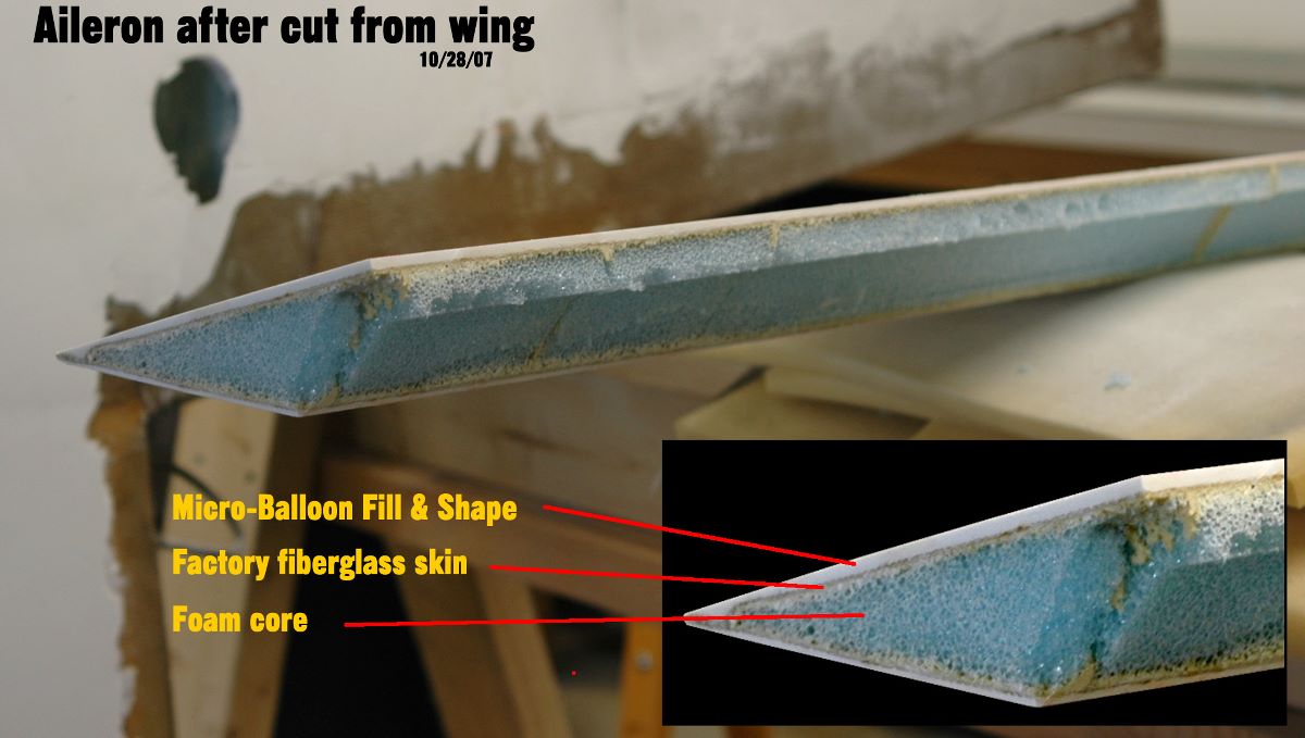
And a quick composite picture of what the fresh cut aileron looks like and what prep work we have on this part. Be sure to click on this picture to see the enlarged version with the annotations.
 |
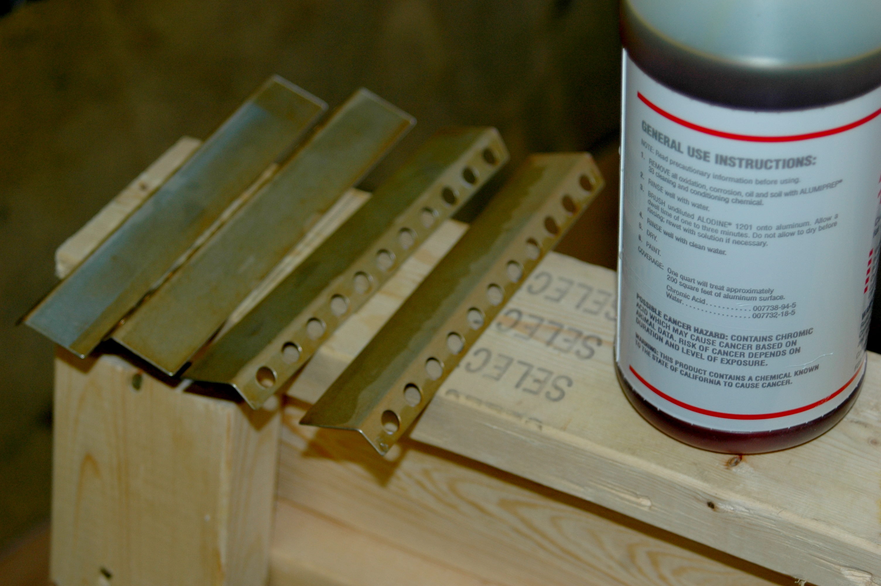
And now for some pictures of the Aileron work. In the first picture, you see our method of anodizing. These are the tabs that will be used in the reinforced areas where the hinges will attach. The next pictures show the counterweight going on and then the final sanding before the hinges are mounted.
 |
 |
 |
![]() Now about the hinges. The manual states that you will need to pull the pins on your MS20001 hinges and rotate them. No problem! But, STOP after you've rotated them and reinserted the pins. DO NOT continue to crimp the ends and safety as the manual state. You will be removing these pins a few more times before you are REALLy ready to safety them in their final location with the ailerons attached. And about the "crimping" of the ends. We haven't figured out how to do that yet. Every time we try to crimp them, we end up work-hardening the pin and it becomes very brittle and breaks. Our solution, as of now, is to bend the pins over at a 90 degree bend.
Now about the hinges. The manual states that you will need to pull the pins on your MS20001 hinges and rotate them. No problem! But, STOP after you've rotated them and reinserted the pins. DO NOT continue to crimp the ends and safety as the manual state. You will be removing these pins a few more times before you are REALLy ready to safety them in their final location with the ailerons attached. And about the "crimping" of the ends. We haven't figured out how to do that yet. Every time we try to crimp them, we end up work-hardening the pin and it becomes very brittle and breaks. Our solution, as of now, is to bend the pins over at a 90 degree bend.
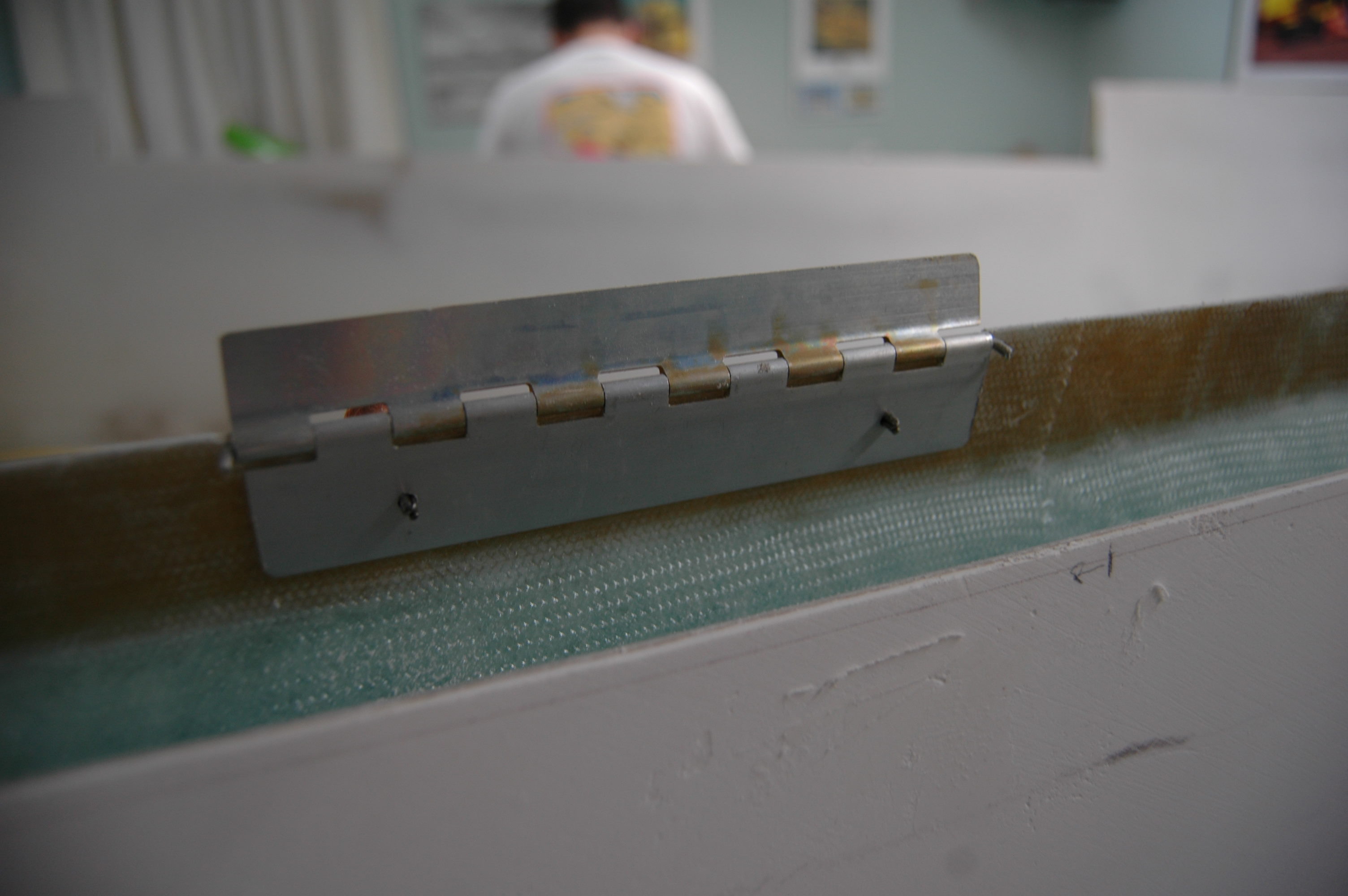
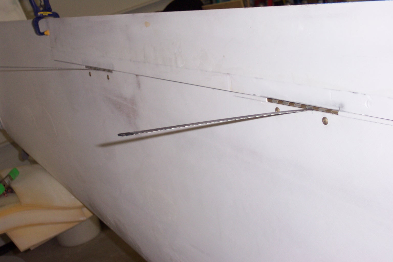
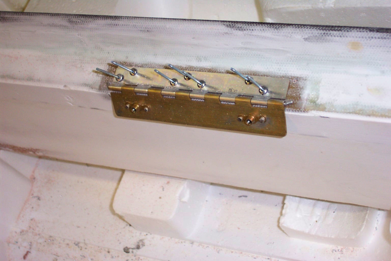
Now we're ready to mount the hinges. The manual is pretty clear on most of this procedure. The two pictures below show the early stages of test-fitting and mounting the hinges. Note the Clecos used to hold the hinge in place while nut plates are marked and added to the hinges. The second picture shows how we tacked the hinges to the ailerons. This is the process of cutting tiny slots under one of the hinge arms and then using a hacksaw blade to push the other half of the hinge up into some Bondo that was placed on the aileron in hopes of getting everything aligned and tacked in place.
 |
 |
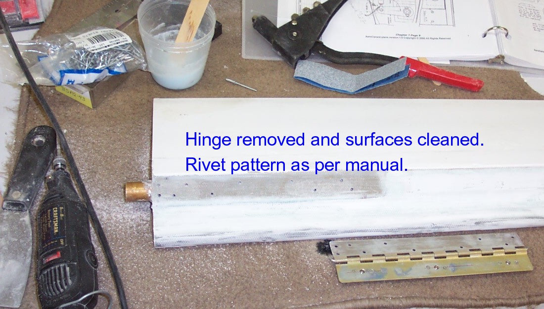
The last part of the hinge mounting process is to remove the ailerons from the wing after the Bondo sets and then mount drill your holes for the pop-rivits and flox and pop-rivit the hinges into their final position. Be sure your rivits penetrate the torque tube where specified in the manual.
 |
 |
 |
 |

| Hidden rudder bell horns | Seems to be a cleaner approach. There appears to be plans available from RAF. Slade has link on his site for RAF to get plans. SOLUTION: We made our own hidden horns out of carbon. |
|
|
||